Atari 2600 Video and Pause Combo Mod
The Combo Mod is a combination Video and Pause Mod made for all Atari 2600 systems.
Disclaimer: I am not responsible for any damage done to your Atari. This mod is designed to allow you to pause your system. The mod will work if performed correctly to a fully functioning Atari. Perform at your own risk.
Tools You Will Need
- Philips Screwdriver
- Soldering Iron and Solder
- De-soldering Tool (De-soldering Iron, Bubble, Vacuum, or Braid)
- Wire Cutters/Strippers
- Needle Nose Pliers
- Drill with 1/4″ bit
- Razor Blade
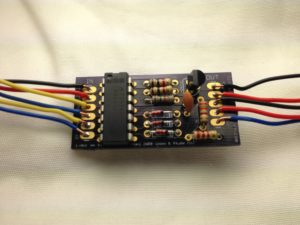
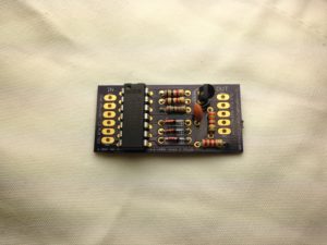
- The first step is to assemble the board. Since the Combo Mod combines the two mods into one board it you will be following the instructions for each mod install separately after the Combo Board is assembled. The spots for each component are clearly marked on the board. You can also follow the picture below.
- Please note the direction for the 14 pin IC, transistor, and 3 Red/Black Diodes. From this view the notch on the IC should be pointing up, the flat face of the transistor pointing left, and the black band of the diode pointing to the right. Also note the resistor values are as follows: 2.2k (Red-Red-Red), 3.3k (Orange-Orange-Red), 1k (Brown-Black-Red), 1.5k (Brown-Green-Red). Again, follow the picture below and once you are finished soldering be sure to clip off all excess leads at the bottom.
- You should have 3 sets of 4 conductor wire included. The color is really up to you but I recommend following the picture below. You will have an extra yellow wire you can get rid of as there are only l11 connections total. The left side of the board are the inputs and the right side are the outputs. You should complete the whole board before you begin installing it.
- Once the board is fully assembled you should begin following the Video Mod instructions for your system from the links below. While you can do these in either order I recommend doing the video mod first because you should test it to make sure everything is working before you start the pause installation.
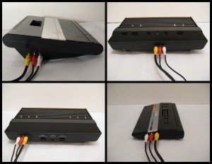
- For the video part you will be connecting 4 input wires for Gnd, +5v, Vid, and Aud as labeled on the combo circuit board. Then you will connect 3 output wires to the RCA jacks for Gnd, Vid, and Aud.
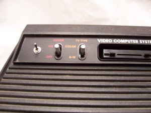
- Note that when you come to the Pause installation instructions you can skip the black and red input wires since we will already have Gnd and +5v from when we connected the Video mod. Also the instructions show two blue wires on the Pause installation guide that are connected to the pause switch but those will be replaced by a black and red wire on the combo mod and are labeled as Sw1 and Sw2.
- Again, I recommend completely installing the video mod first and then testing it before you begin the pause installation. Once that is completed be sure to test everything before putting it back together. Then fire up a game in clearer composite video and feel free to pause it and get yourself a cold drink, you’ve earned it 🙂 Then leave me a comment below and let me know how it went….