Disclaimer: I am not responsible for any damage done to your Atari. This mod is designed to remove the RF output. The mod will work if performed correctly to a fully functioning Atari. Perform at your own risk.
Turn the Atari over and remove the 4 screws. Set them aside for later. Remove the main board out of the console by disconnecting the RF cable shown below. Take off the black foam covers on the switches and set them aside for later. Take the foil tape off the switches and throw it away.
Using the need nose pliers, bend up the 4 tabs around the metal case. Remove the metal casing (top and bottom) and throw it away. You should now have the main board like this ready to modify.
In the middle of the board is a transistor you will have to remove. It is labeled Q201 on some 4 switch versions and Q202 on others. It’s shown in the picture on the left. Simply cut all 3 leads of the transistor and throw it out. Make sure none of the leads coming out of the board are touching each other. Then you need to remove the 4 pins to the RF modulator (metal box with small circuit board attached). Simply cut the pins and bend them up so they are out of the way, or you could break off the small circuit board entirely because it is no longer used.
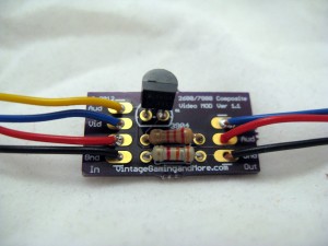
Now it’s time to assemble the circuit board. Just follow the picture below and solder in the transistor, 2.2k Resistor (Red-Red-Red), and 3.3k Resistor (Orange-Orange-Red). The components are labeled on the circuit board so it should be pretty easy to see where they go.
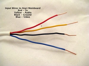
You should have two pieces of 4 conductor wire. First, strip off the white sheathing. You can save about an inch of it to help group the wires together if you like. Next, throw out one of the yellow wires. Now you should have two groups of wires. A group of 3 output wires (Red, Black, and Blue), and a group of 4 input wires (Red, Black, Blue, and Yellow). With the new wire I use, Blue replaces Green and Yellow replaces White in the pictures. The group of 4 wires are the input wires that go to the main board. Strip about 1/2″ off of both ends of the input wires and attach them to the mod kit. Black is the GND, Red is +5v, Blue is Video, and Yellow is Audio.
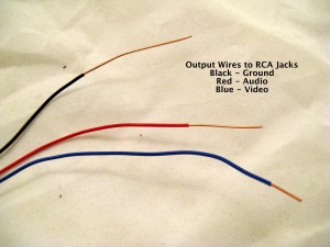
The group of 3 wires are out wires that attach to the RCA jacks. The output wires should be stripped to different lengths as in the picture. About 1/2″ for Blue, 1″ for Red, and 2″ for Black. On the output side of the mod kit, Black is for GND, Red for Audio, and Blue for Video.
First you need to use your de-soldering tool and clean out the holes where the RF modulator pins were. Then connect the input wires and solder them in from underneath as shown in the picture. Make sure the black wire goes to pin #1, red to pin #3, and blue to pin #4. Then attach the yellow wire to the base of the resistor as shown (R206). You could also use the open hole on the capacitor immediately to the right (C208), as they are connected to each other. Now the main board is done.
Take the bottom half of the case and put a piece of masking tape where you want the RCA jacks to go. Use a ruler and marker and make 3 dots on the tape 1/2″ apart. Then drill 1/8” pilot holes on the dots, and use the 1/4” drill bits on the holes to make them ready for the RCA jacks. The tape and marker are just extra precautions, you could also just drill the holes if you want.
Attach the RCA jacks by mounting them into the case with the ground ring and nut on the inside. Make sure they are tight. Have the ground ring holes be at or near he top and bend them down to make soldering easier. Take the Black output wire with the longest amount of bare wire and solder it to all three ground rings like in the picture below. Take the Red wire and solder it to the Red and White jacks. Take the Blue wire and solder it to the yellow jack.
Now you are ready to put the mainboard into the case. First you need to adjust the color pot on the bottom left of the mainboard. Attach the RCA and power cables and use a game with nice bright colors you are familiar with like Pitfall or Frogger. Adjust the pot so the colors are just right. Then peel off the bottom of the double sided tape and stick it to the right side of the bottom case. Replace the foam dust covers, top case, and the screws and you are ready to play your Atari with composite video! Please leave a comment below and let me know how it works!
18 thoughts on “Installation Guide – 4 Switch”
Just installed this kit, Very happy with the way it turned out, looks like it came from the factory like this and works Great.
Thanks for making this Cool product and breathing new life in the old 2600.
Thanks for making this Cool product its useful.
This is a great product. I had never soldered I piece of electronics in my life. Picked up a soldering iron and after a couple of you tube videos I felt pretty comfortable. I had my mod kit installed in about 2 hours in my 4 switch 2600. Now all the kids are down playing missile command on my 70inch. It worked like a charm and was super easy.
Thanks,
Rob
This is an excellent modification for the 2600! It was easy to install and the directions are very clear. Now I can play my Synthcart through a PA system or an amp. The picture also looks a lot nicer than that of the r/f switch one. Thanks for the great mod!
this was great start to finish 2 hours never have i done something like this but it was fun and the step by step was easy to follow
Just finished the Atari 2600 mod in under 2 hrs. Works fine coupled to my home theater Epson projector. Components of kit were good quality and installation instructions we simple enough for the novice. Now if I can just remember how to play all those games!
thank you so much for making this mod. took me about 2 hours from start to finish and it works great! only thing I would say is need a little more clarity as to connecting the yellow wire on the resistor (R206), maybe a better close up picture. i soldered my yellow wire on to both the resistor base and the capacitor next to it as they are bridged together like you said.
thank you very much for your instructions…..extremely easy instr. to follow..i finally got my atari working…missed it very much and my grand kids cannot believe that these were the games i played when young…
but they injoyed it……
Great little mod. The instructions are clear and easy to understand. Works just as it should. What more can you ask for?
I ordered a kit from you years ago and finally assembled everything today. I sure did a sloppy job, but it totally works!
One thing–I installed it on a Vader and the board layout is a little different than the 4 switch you show in the pictures. Thankfully I was able to figure out what to do using the Atari Service Manual you have on the site! Thanks!
Great video mod. Works great, simple to accomplish !!!
Thank you to preserve old stuff!I did one of my first bgiger projects (a memory resident 6502 assembler/monitor) on an Atari 800XL, some experimental stuff later on an Atari 130XE (which i bought from the money i got for the 6502 assembler/monitor) like a sound digitizer or a data interface to transfer stuff from/to a C64 and eventually ended up with a Atari 1040STe where i had my first big own project the Thing desktop.Now nearly 20 years later i still work as a professional software developer and run several websites on my own servers but unfortunately i don’t have the 8 bit machines any longer. Only the 1040STe is still alive and from time to time i just have a look at it to remember my roots.
Installed video modification today – simple and easy to install and works great.
Just installed and works great!
Just wrapped up the combo kit works great. Just make sure to read the full page on installation before tapping the link to pause instructions or you will miss the point about not doing the +/- because its already done when doing the a/v install 1st.
Holy smokes it worked! Kaboom was my ultimate test after finishing the install. On the told setup – Kaboom would start to crash the video after a few minutes. Video would just get all hazy and then the game would become unplayable.
Now with this new setup installed… Kaboom played perfectly for as long as I wanted to play. No issues yet!
Well done! Thanks for this product and guide!
Just did the video Mod. Works great! Thank you. Much better video resolution now.
Thanks, I am a novice with electronics and these were easy to follow instructions. So far everything works great.
Minor point – A couple photos could be updated to reflect the current wires ( blue not green, yellow not white?)


")


")


Just installed this kit, Very happy with the way it turned out, looks like it came from the factory like this and works Great.
Thanks for making this Cool product and breathing new life in the old 2600.
Thanks for making this Cool product its useful.
This is a great product. I had never soldered I piece of electronics in my life. Picked up a soldering iron and after a couple of you tube videos I felt pretty comfortable. I had my mod kit installed in about 2 hours in my 4 switch 2600. Now all the kids are down playing missile command on my 70inch. It worked like a charm and was super easy.
Thanks,
Rob
This is an excellent modification for the 2600! It was easy to install and the directions are very clear. Now I can play my Synthcart through a PA system or an amp. The picture also looks a lot nicer than that of the r/f switch one. Thanks for the great mod!
this was great start to finish 2 hours never have i done something like this but it was fun and the step by step was easy to follow
Just finished the Atari 2600 mod in under 2 hrs. Works fine coupled to my home theater Epson projector. Components of kit were good quality and installation instructions we simple enough for the novice. Now if I can just remember how to play all those games!
thank you so much for making this mod. took me about 2 hours from start to finish and it works great! only thing I would say is need a little more clarity as to connecting the yellow wire on the resistor (R206), maybe a better close up picture. i soldered my yellow wire on to both the resistor base and the capacitor next to it as they are bridged together like you said.
thank you very much for your instructions…..extremely easy instr. to follow..i finally got my atari working…missed it very much and my grand kids cannot believe that these were the games i played when young…
but they injoyed it……
Great little mod. The instructions are clear and easy to understand. Works just as it should. What more can you ask for?
I ordered a kit from you years ago and finally assembled everything today. I sure did a sloppy job, but it totally works!
One thing–I installed it on a Vader and the board layout is a little different than the 4 switch you show in the pictures. Thankfully I was able to figure out what to do using the Atari Service Manual you have on the site! Thanks!
Great video mod. Works great, simple to accomplish !!!
Thank you to preserve old stuff!I did one of my first bgiger projects (a memory resident 6502 assembler/monitor) on an Atari 800XL, some experimental stuff later on an Atari 130XE (which i bought from the money i got for the 6502 assembler/monitor) like a sound digitizer or a data interface to transfer stuff from/to a C64 and eventually ended up with a Atari 1040STe where i had my first big own project the Thing desktop.Now nearly 20 years later i still work as a professional software developer and run several websites on my own servers but unfortunately i don’t have the 8 bit machines any longer. Only the 1040STe is still alive and from time to time i just have a look at it to remember my roots.
Installed video modification today – simple and easy to install and works great.
Just installed and works great!
Just wrapped up the combo kit works great. Just make sure to read the full page on installation before tapping the link to pause instructions or you will miss the point about not doing the +/- because its already done when doing the a/v install 1st.
Holy smokes it worked! Kaboom was my ultimate test after finishing the install. On the told setup – Kaboom would start to crash the video after a few minutes. Video would just get all hazy and then the game would become unplayable.
Now with this new setup installed… Kaboom played perfectly for as long as I wanted to play. No issues yet!
Well done! Thanks for this product and guide!
Just did the video Mod. Works great! Thank you. Much better video resolution now.
Thanks, I am a novice with electronics and these were easy to follow instructions. So far everything works great.
Minor point – A couple photos could be updated to reflect the current wires ( blue not green, yellow not white?)
Thanks again!