Disclaimer: I am not responsible for any damage done to your Atari. Please follow the instructions carefully and use the contact form if you have any questions.
Turn the Atari over and remove the 8 screws. Set them aside for later. Disconnect the RF cable if it is still attached to the switchboard. Then take both the switchboard and main board out of the case. Take off the black foam covers on the switches and set them aside for later.
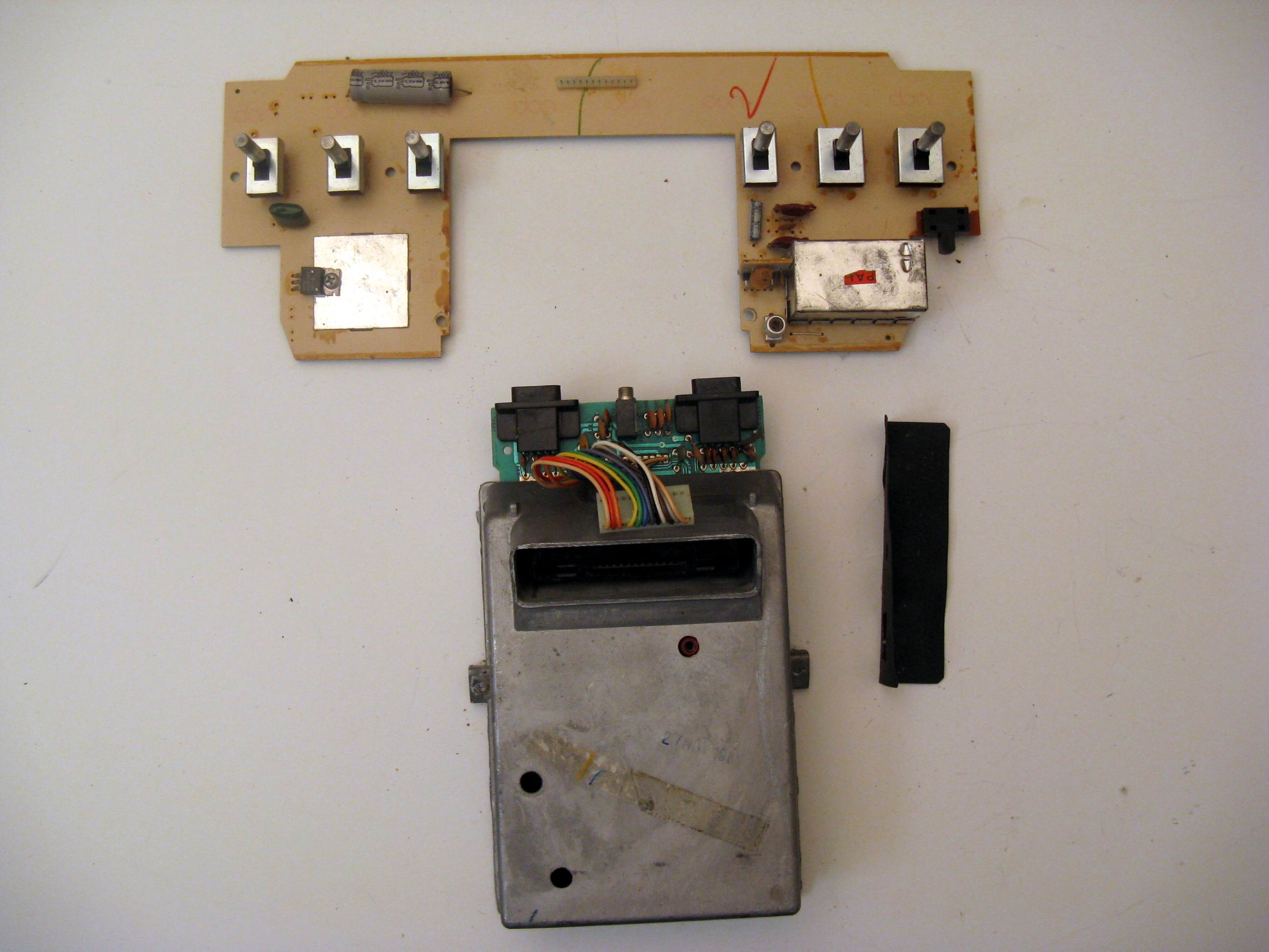
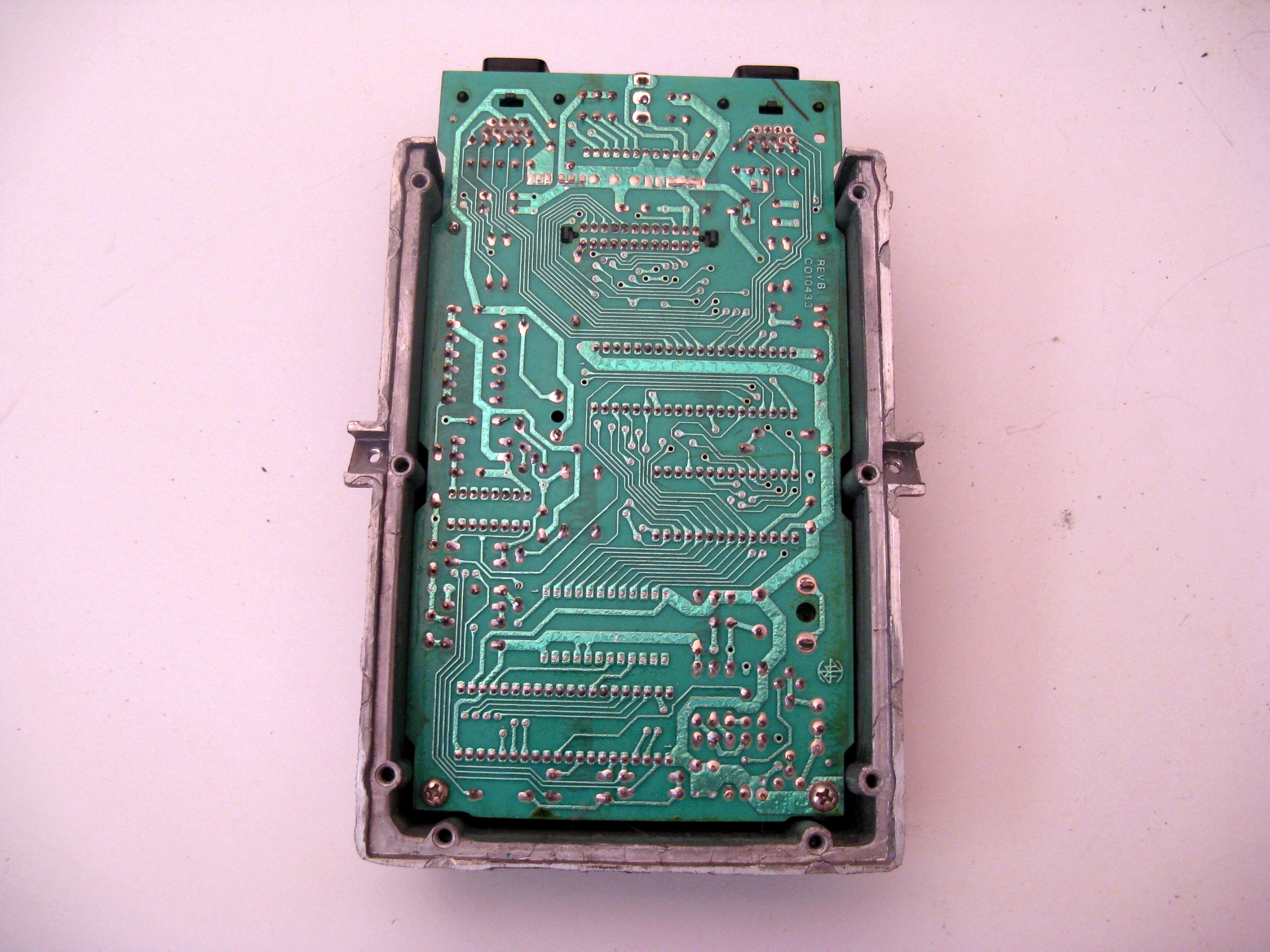
Unplug the ribbon cable and remove the two screws on either side of the main board case. This will disconnect the main board from the switchboard. Also set aside the dust cover for the joystick and power ports. Now take the metal casing and turn it over. Unscrew the 6 screws there and throw away the bottom part of the metal casing.
Now remove the two screws connecting the main board to the top casing. Take the main board out and you are ready to be start replacing components.
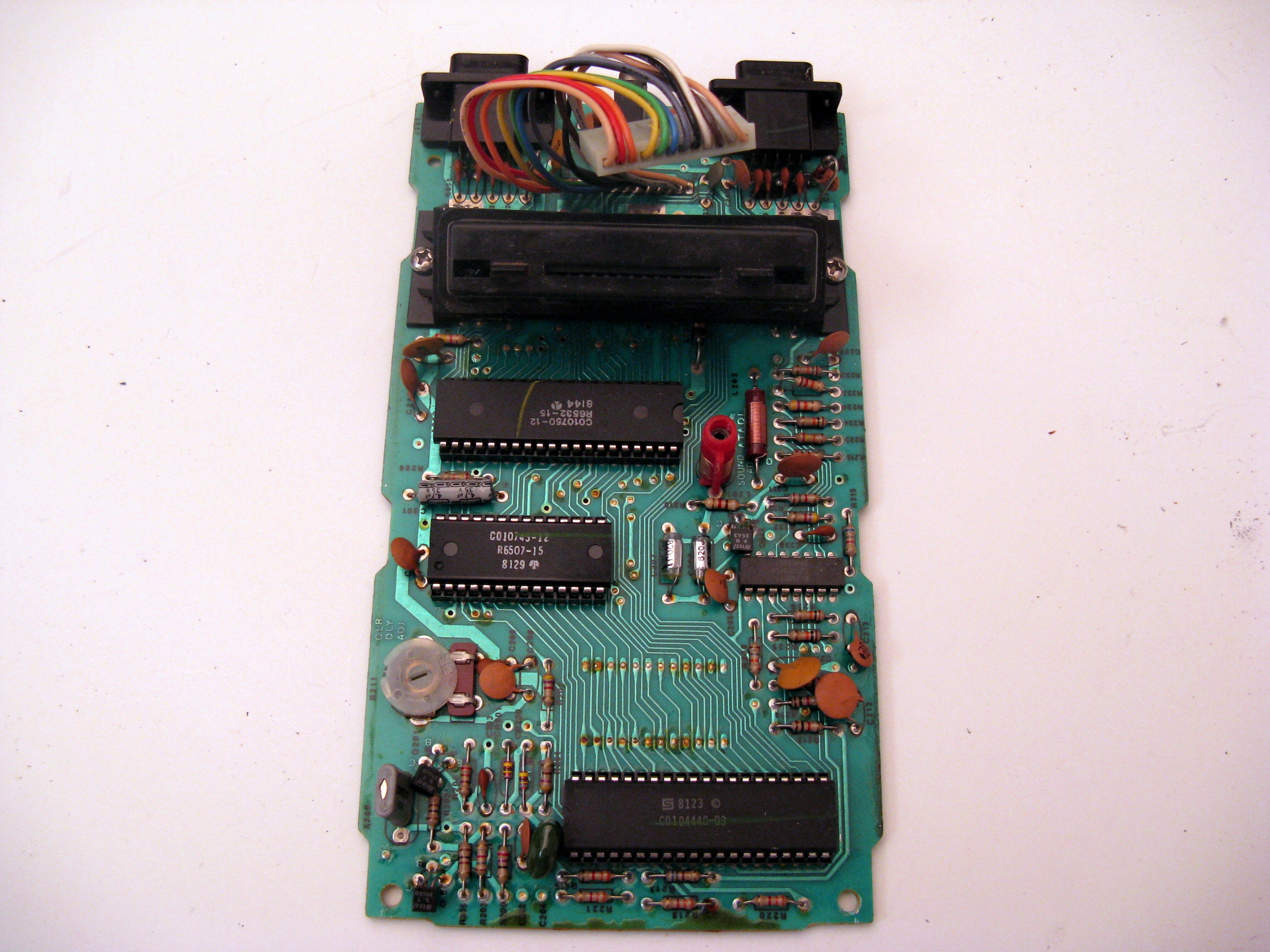
The image below has some mods installed, but it will give you an idea of what components you will be replacing (note there are different models and sometimes the style of capacitor you are replacing may look different but that is OK, more details below)
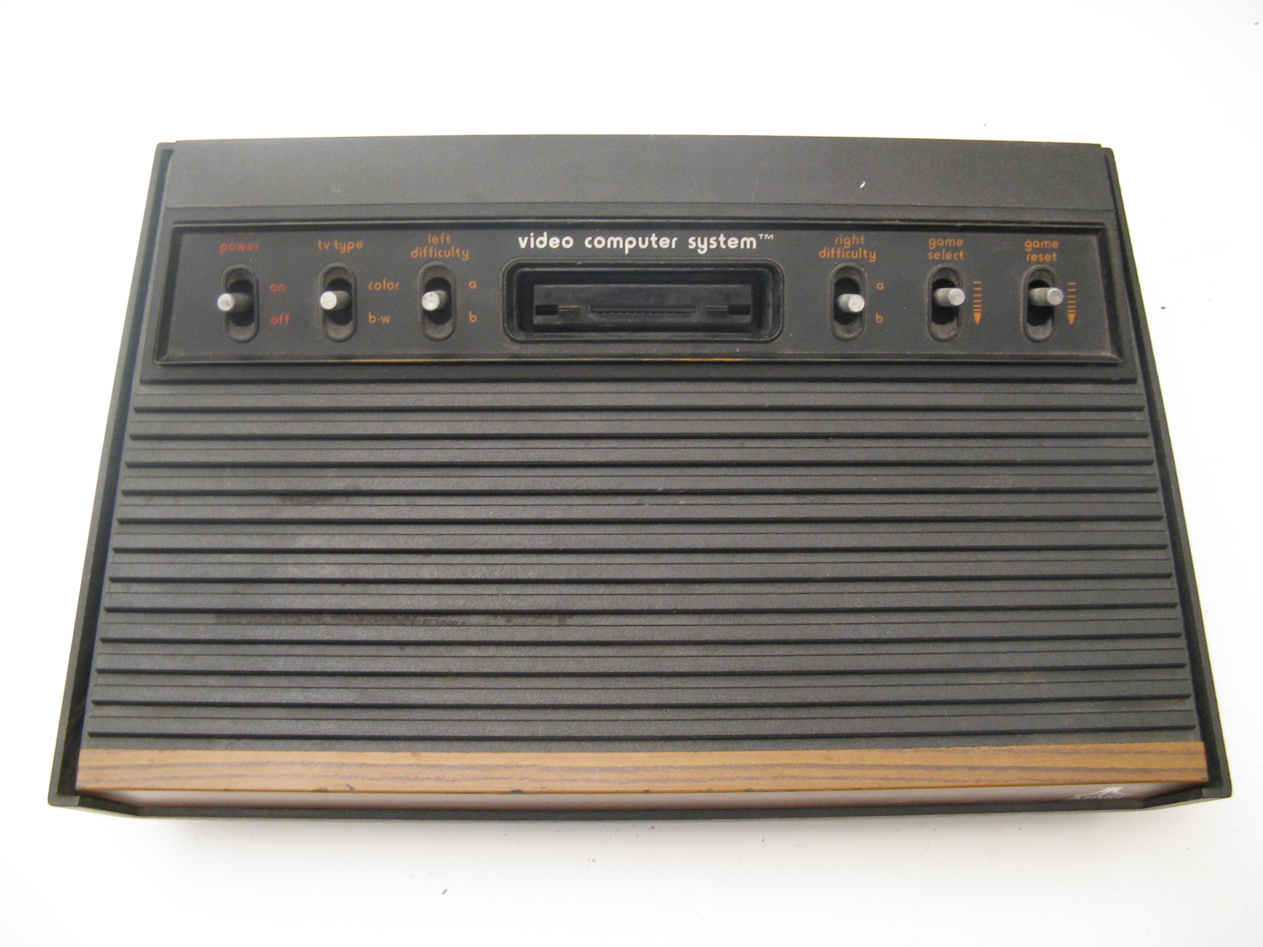
Atari Light 6 Switch Model
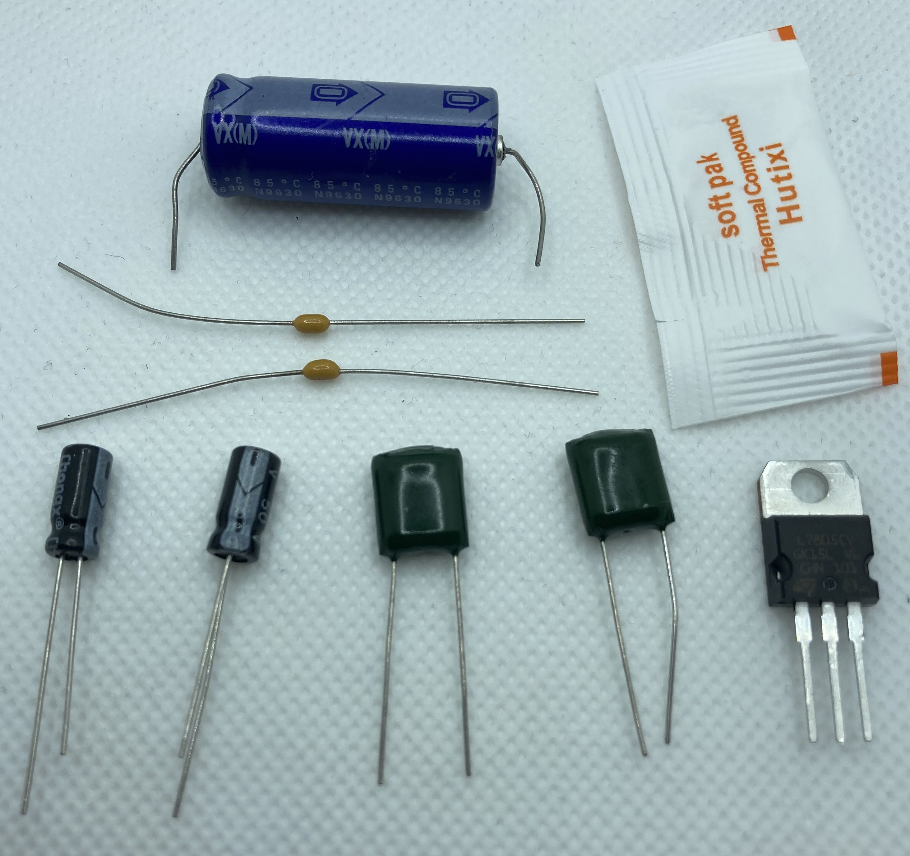
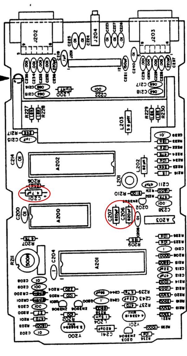
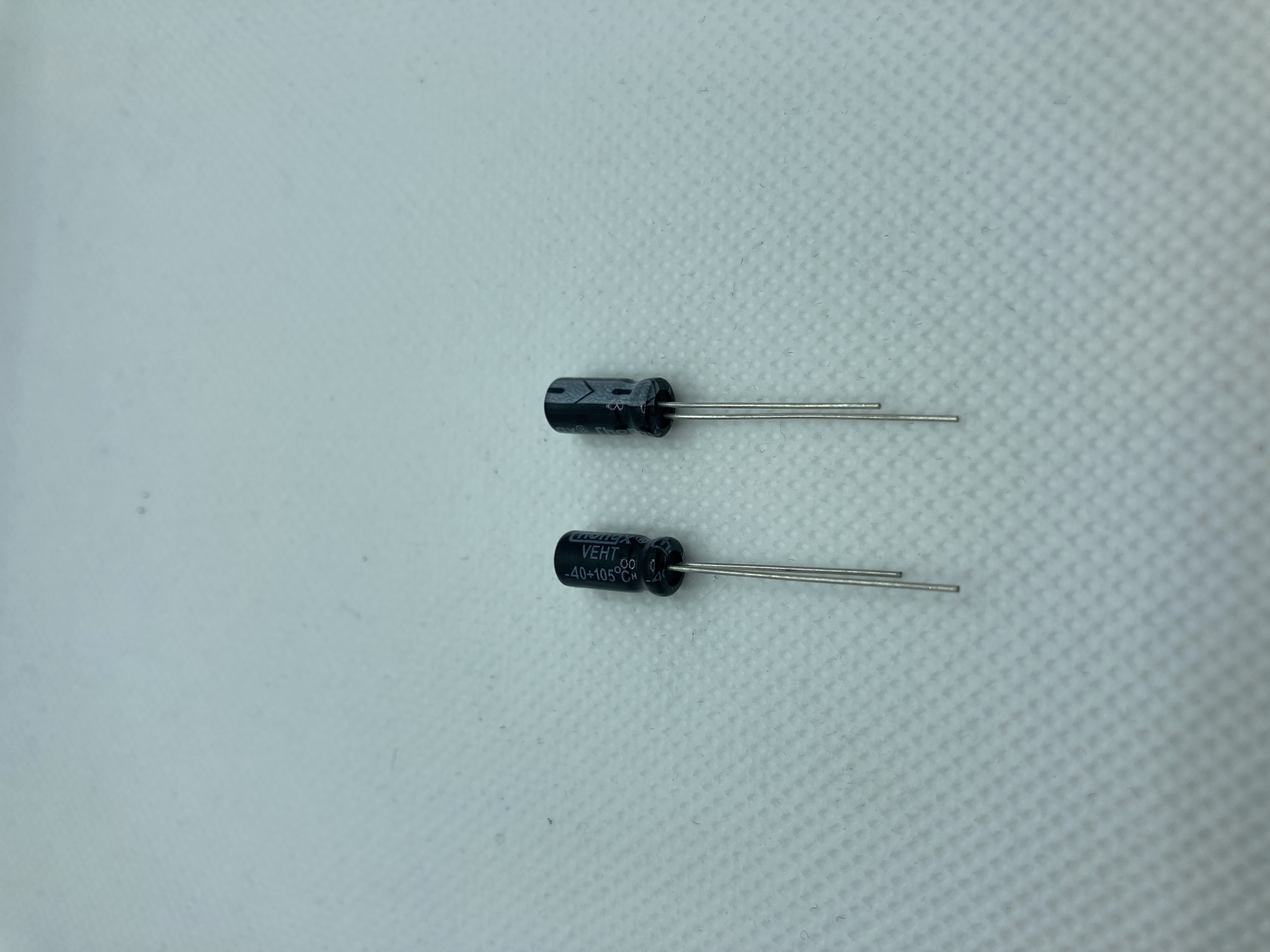
The silkscreen image below (click to view higher res image) shows the locations of C201, C206, and C207 on the main board. You will need to de-solder and remove the existing components and replace them. C201 will use one of the two small black radial capacitors in the left picture below. Please note this capacitor is polarized so it has a positive and negative lead and must be installed the correct way. The longer lead is the positive and the shorter lead (side with the gray stripe) is the negative. The silkscreen image on the left shows the positive side is on the right toward the center of the board (The writing on the silkscreen is upside down so the orientation matches the pictures above where the joystick connectors are at the top).
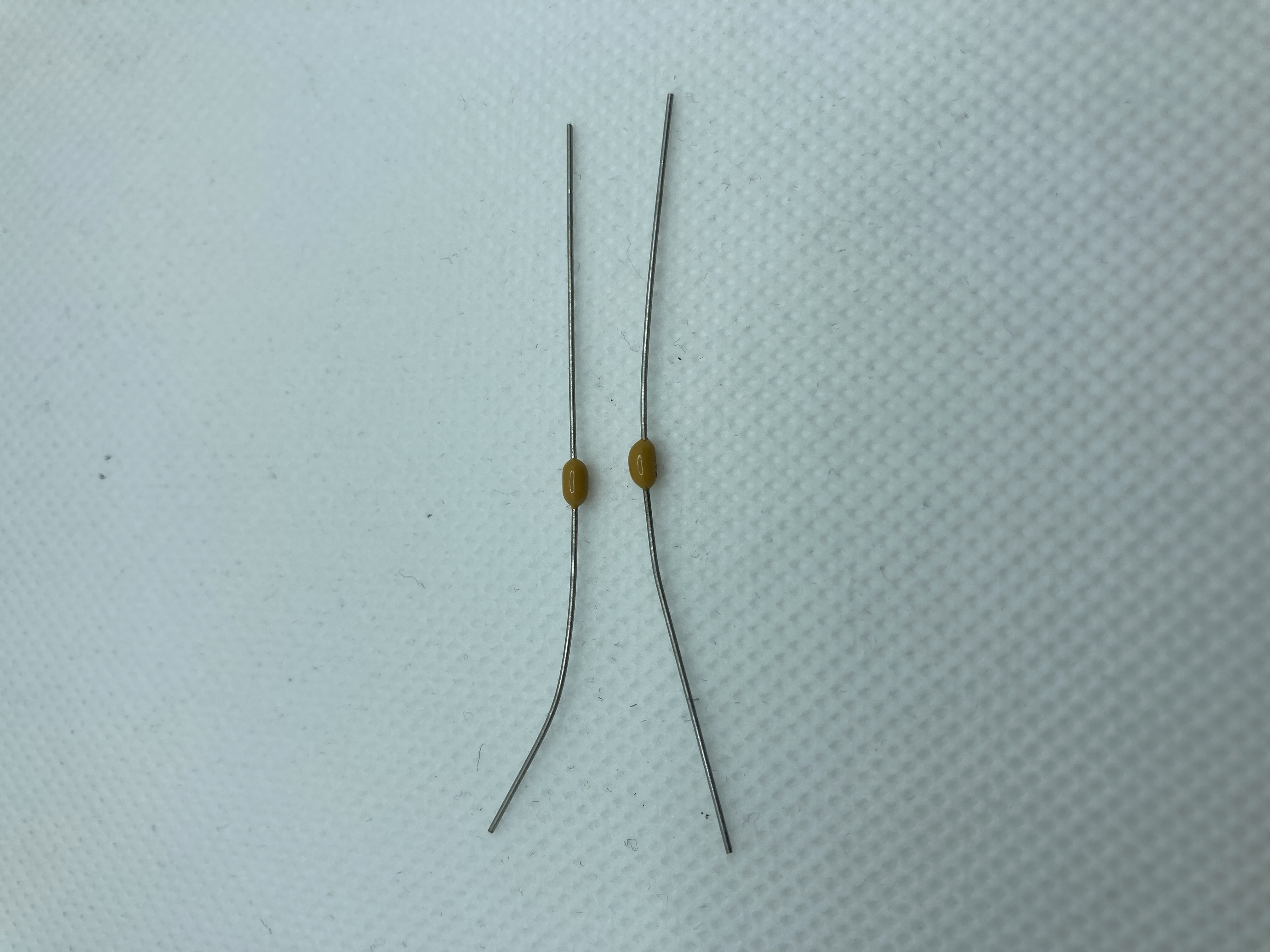
You should have two of the smaller, yellow axial capacitors on the right that will replace C206 and C207 in the audio circuit. They are not polarized and can be installed in either direction. These will look different then what is currently installed on your Atari but they are a better type of capacitor compared to the original and are less prone to failure.
6 Switch Mainboard
Small Radial Cap
Small Axial Audio Cap
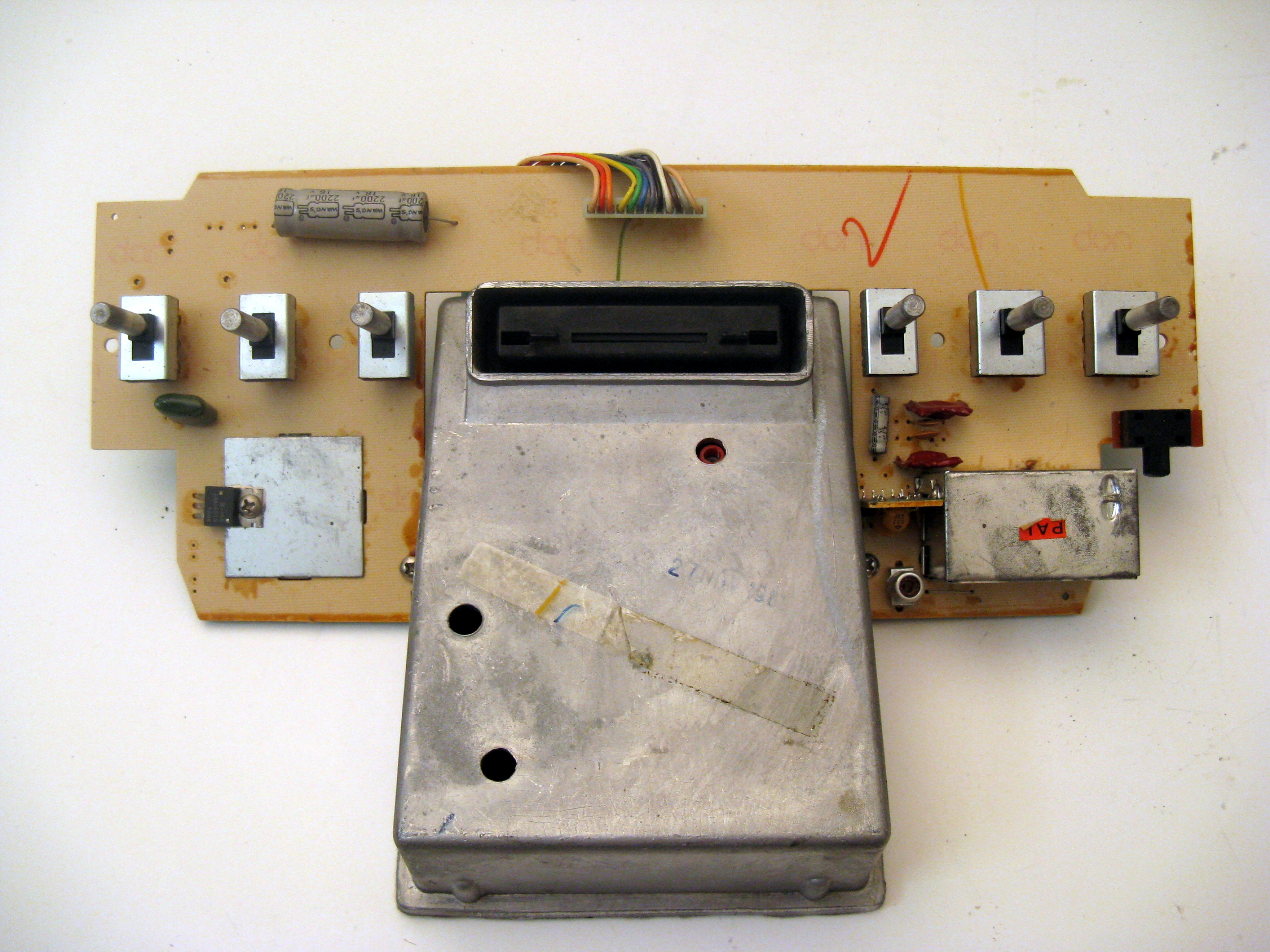
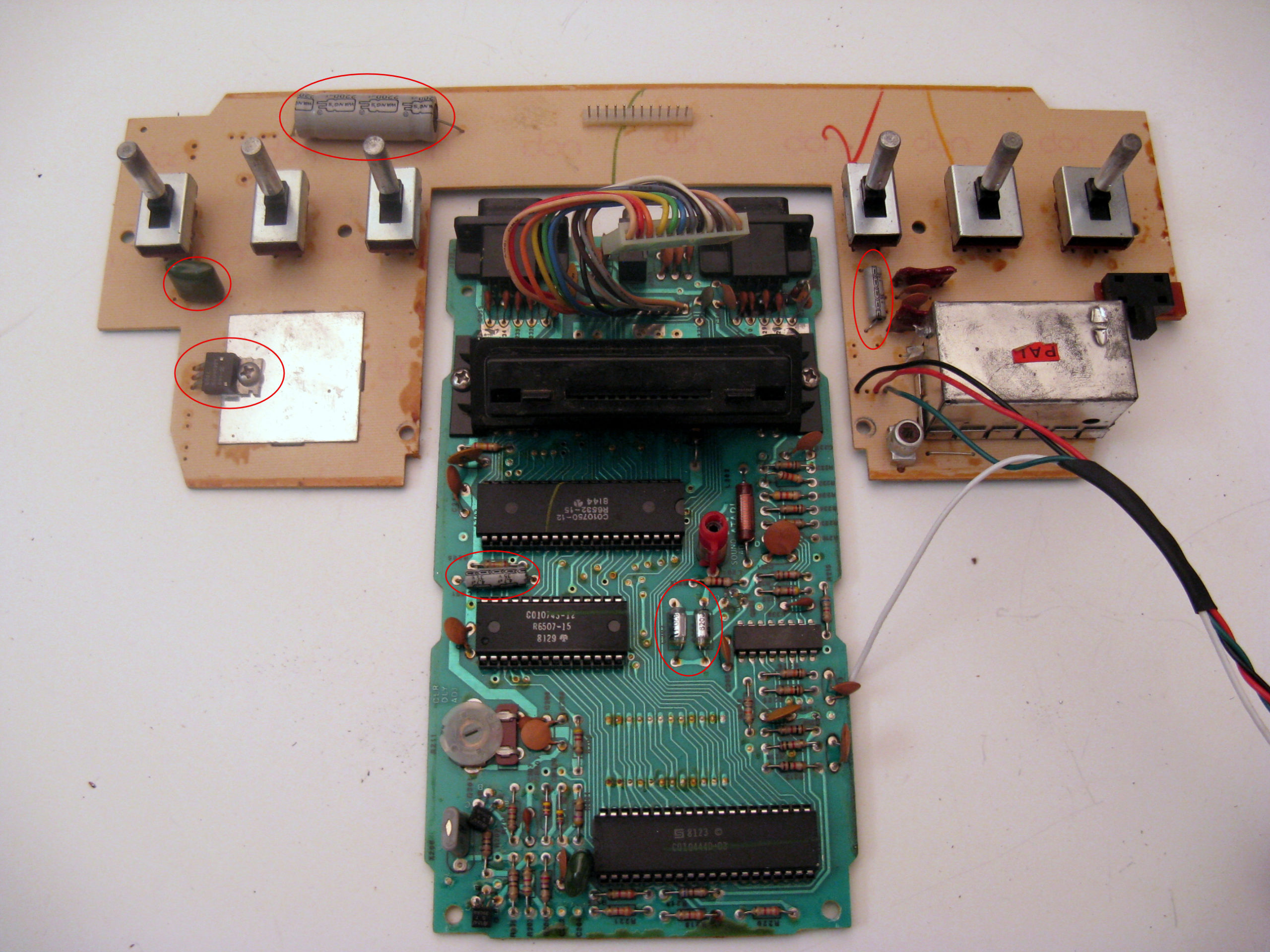
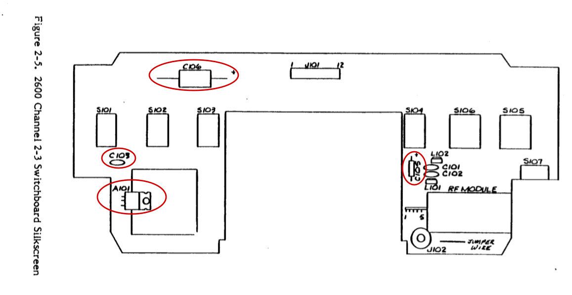
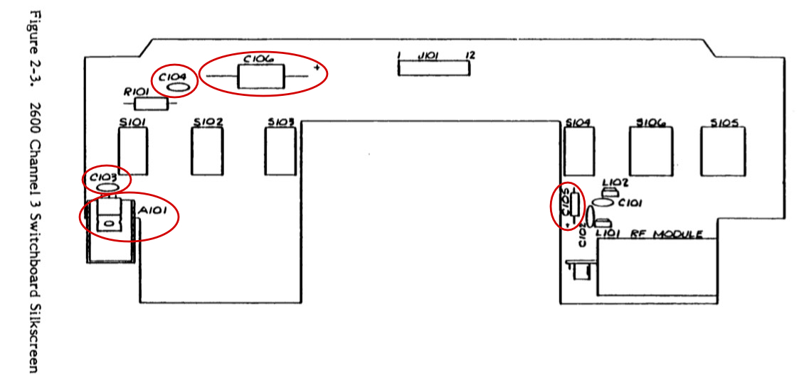
Now take the switchboard and note the places where you will be replacing the capacitors. The images below are of two different styles, the first is known as a “light sixer” and the second is a “heavy sixer”. The light sixer board is much more common, note that these do not have C104 so if you have this model you will have an extra “Chiclet” capacitor with your kit that will not be used.
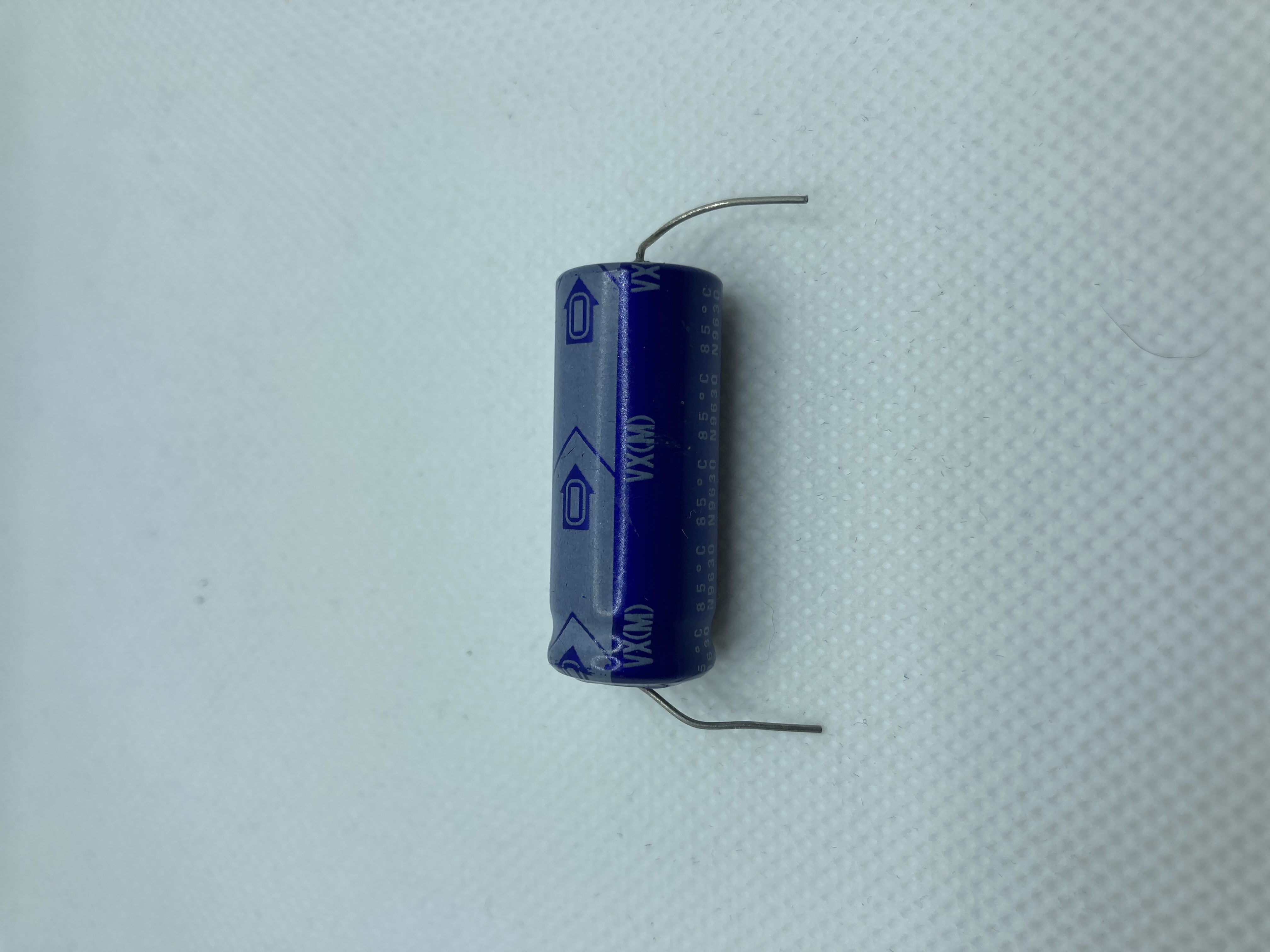
Start with C105, that uses the other polarized small black capacitor shown above. Again, note the the correct side for the positive lead, in this case goes toward the bottom. Next replace the large C106 axial capacitor with the one. This is polarized as well, again note the the correct side for the positive lead based on the circuit board marking. The arrow on the capacitor points to the negative side. Be sure to install it correctly as reversing these will blow the capacitor and could damage your system.
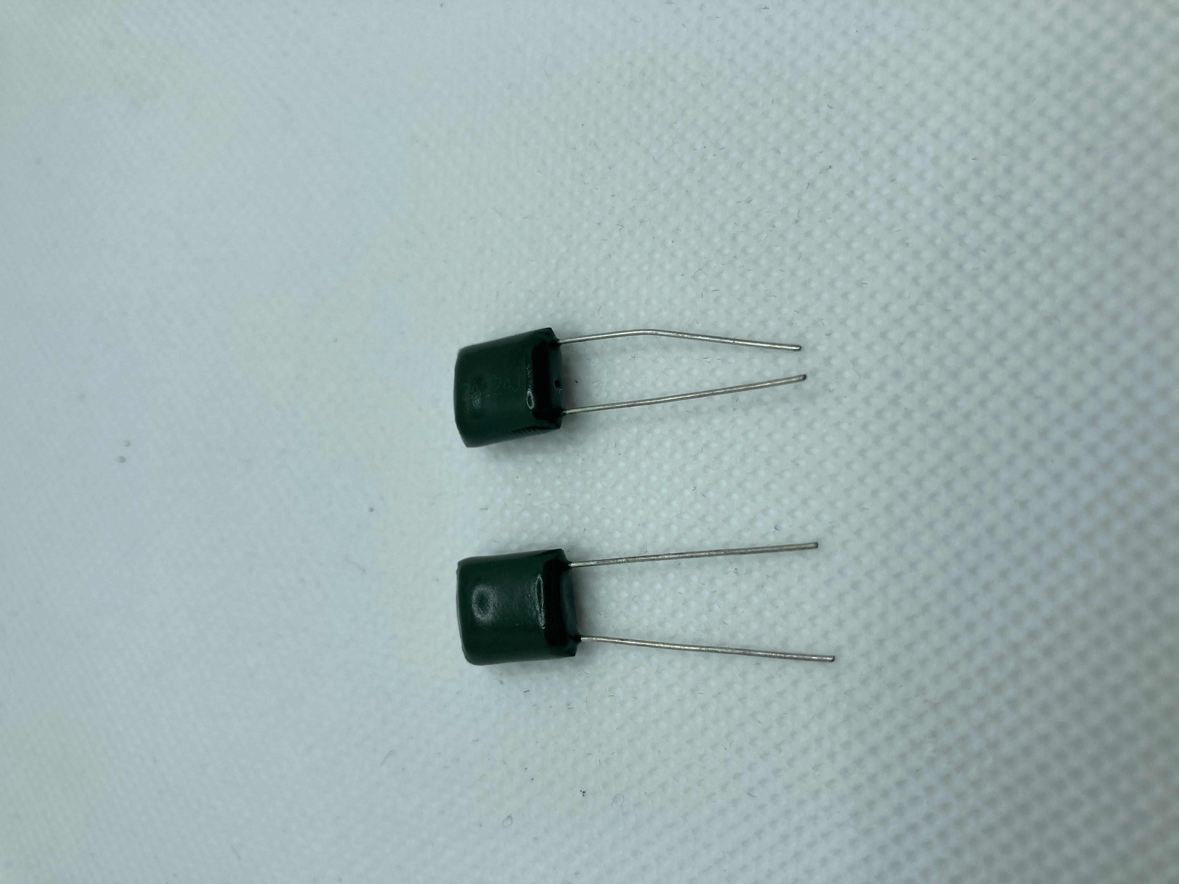
Replace C103 and C104 (if present on heavy sixer only) with the two green “Chiclet” capacitors, these can be installed in any direction.
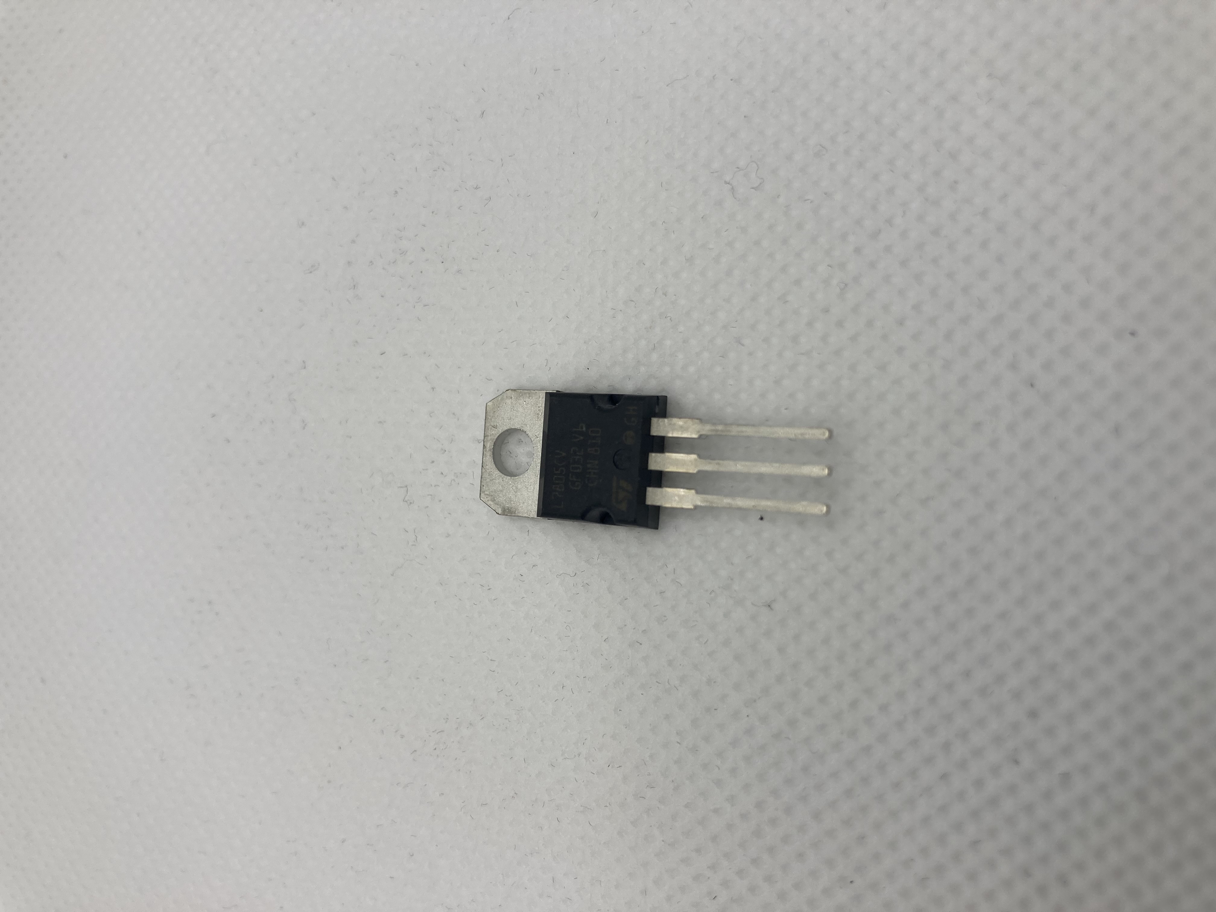
Lastly, replace the black 3 pin voltage regulator at A101. Be sure it is oriented the same way with the screw hole and use a small amount of thermal paste between the bottom of the chip and the board. You should not use the whole packet of paste.
Light Sixer
Heavy Sixer
Large Axial Cap
Chiclet Cap
Regulator
Now you are ready to put everything back together. Optional: While the cover is off you can also adjust the color potentiometer on the bottom left of the main board. It is the big plastic circle and is the only pot on the board. Attach the power, ribbon, then hook it up to the TV and use a game you are familiar with to adjust it so the colors are just right. A game like Frogger or Pitfall with a variety of bright colors is ideal.
Now unplug everything, and put the top metal casing over the main board and secure it with the two screws. Then screw in the switch board to the main board and put them both in the case. Be sure to put the dust cover back on the plugs and joystick ports and the foam covers on all the switches.
Now put the top cover back on, and put back the 8 screws back in. Start with the two in the middle. After that you are done and ready to enjoy your Atari! Also be sure to check out my Atari mods for composite video and a pause switch here. Please leave a comment below and let me know how you made out!