Atari 2600 LED Mod Kit Installation Guide for 4 Switch and 6 Switch Systems
This guide will give you step by step instructions for how to install our LED Power Light Kit into your existing 4 Switch and 6 Switch 2600 System. Where you place the LED light is entirely up to you, the pictures just give you one example. Here is a list of the tools you will need:
- Screwdriver
- Soldering Iron and Solder
- Wire Cutters
- Drill and 1/4″ drill bit
-
First you will need to unscrew the case and remove the mainboard from the system. The 6 switch systems have 8 screws on the bottom and the 4 switch have 4. After you remove the screws you can take the mainboard out of the case by removing the coaxial plug. Set this aside and we will come back to them after we have drilled the holes to mount the LED.
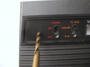
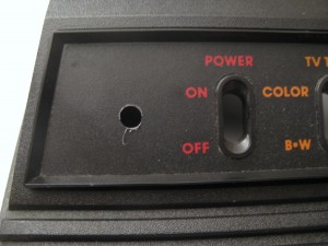
- Now find the place where you want to mount the LED on your system and drill a 1/4″ hole. Make sure you are happy with where LED is. You will need enough wire to attach to the 3 pin chip in the lower left hand side of the mainboard. The hole is probably a little small at this point so you might night to take a razor blade or something and shave the edges a bit.
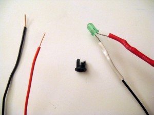
- Now assemble the LED. Remove the red and black wire from the white casing but save some of the casing for later. Solder one end of the resistor to the long end of the LED and the other end to the red wire. Solder the short end of the LED to the black wire. Use the casing to cover the metal leads of the LED and the resistor so no bare wire is showing except for a little at the top, like in the picture below. I usually secure the bottom of the white casing with black electrical tape to make sure it stays in place.
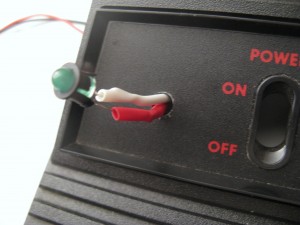
- Place the LED mounting bracket over top of the LED so the tabs snap into place. Then feed the wire through the hole in the cover from the top and push it in so that it fits snug onto the case. If it doesn’t seem to be fitting you probably need to shave a little more off the edges.
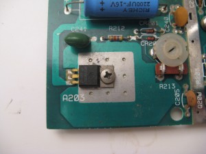
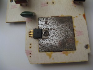
- Next we are going to attach it to the main board. Here is a look at the area we will be dealing with. The 4 switch example is on the left, the 6 switch on the right. notice we are dealing with the same component on both board, the 3 pin voltage regulator.
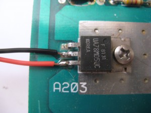
- Now you need to solder the two wires into place. Make sure you use enough solder to get a firm connection to the pins, but not so much so that they are shorted together. Connect the Black wire to the middle pin and the Red wire to the bottom pin. Believe it or not, after that you are done! Put the board back in the case, attach the coaxial cable, and screw everything back in the case and enjoy your new mod! Show it to your friends, they will be envious. Leave me a comment and let me know how it works for you. If you have any questions or problems use the contact page.
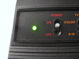
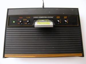
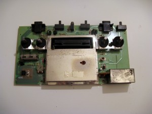
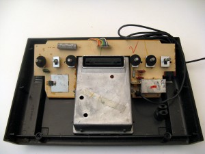
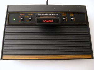
I did a similar LED mod on my 4 switch. I used a 12V green LED lamp from Radio Shack (series resistor included). Since the resistor could not be adjusted to brighten the LED for 5V, I opted to connect the lamp to the deregulated input between the power switch and the 7805 regulator. I chose to solder directly to the thick traces on the motherboard, using a few inches extra length of wire than the 4″ leads lamp came with, to reduce the risk of ripping out the traces. It was nice and the green luminous glow is pleasant to the eyes.
hi good for me it work
If Atari had put an LED indicator on the 2600 back in the day, it would have been red. Virtually all LEDs were red back then.
Hello,
great this tutorial!
clear, precise and simple.
thank you very much for your work.
Have a good day